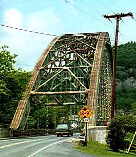
Samuel Morey Memorial Bridge. |
|
|
Site: V14-7 / N13-5 |
National Register Nomination Information:
DESCRIPTION: Gracefully spanning the Connecticut River as it lazily flows between the two small rural communities of Orford, New Hampshire, and Fairlee, Vermont, the Samuel Morey Memorial Bridge is an excellent and unaltered example of a late period tied, through-arch, single span highway bridge of steel construction. Erected in 1937-38 to replace an aging wooden structure that had been severely damaged by flood waters in 1936, the 432 foot span is notable for its two great segmental steel arches that spring to a height of 85 feet above the roadway suspended below. Whether viewed from the north or south within the river's pastoral valley, this pair of light green painted arches that appear above the adjacent tree tops, between the sharply vertical, craggy stone face of the Fairlee Palisades and the lush rolling foothills of Orford and Sunday Mountain, proudly proclaim the majestic structure's presence. Here is an honest, functional expression of engineering that is compatible and at peace with its natural surroundings; a structure that clearly reflects the era within which it was built; and a structure and setting that today appear almost unaltered from the day when the bridge was completed and dedicated in June 1938. With clarity and purposefulness, the span combines structural steel shapes and related components to address the need of crossing a major river with a single span, while at the same time contributing to the overall beauty of the immediate area, rather than detracting from it. At one time, the Orford-Fairlee bridge was one of five steel through-arch bridges listed on the New Hampshire Historic Bridge Inventory, but as of 1997 only four still exist, including two others also spanning the Connecticut River, at Woodsville-Wells River and at Chesterfield-Brattleboro. The future of those two bridges is uncertain at present, which means that the Orford-Fairlee bridge could well become the last of its type linking New Hampshire with Vermont. The Connecticut River runs remarkably straight as it passes between the two village areas, flowing southwesterly. Within the vicinity of the bridge, the river maintains a normal channel width of approximately 300 feet. From flat terrain facing both sides, lightly wooded banks drop down steeply to the water's surface, perhaps thirty-five feet below. Immediately under the structure, along the narrow strips of land separating the water's edge from the bridge's abutments, the shoreline on both sides is riprapped with large pieces of cut granite, probably left from the abutments and center pier of the wooden covered bridge that crossed the river here prior to the erection of the present span. The bridge's abutments and their wing walls, lightly styled in a period "Art Deco" or "Moderne" style, are constructed of poured-in-place reinforced concrete and recede back into the river's banks in three stepped sections. Additionally, the abutments help to elevate the 24 foot wide roadway as it approaches from both directions, and, in fact, the Fairlee side of the crossing including the top on the riverbank, is approximately 15 feet higher than the Orford side. Recently the original white painted round wooden guard rail posts and braided wire cables that appear in photographs taken shortly after the bridge's completion have been removed. Now, to protect motorists from leaving the roadway as they approach the crossing from either side, square pressure-treated wooden posts and galvanized cold-formed steel guard rails line the 24 foot traveled way on both sides of the river, immediately back from the concrete abutments. This is the only noticeable change that has occurred to the span or its setting during the fifty-nine years since its completion, other than the addition of a street light at mid-point on the bridge. The original square-cut granite curbing, installed the time of the bridge's construction, is still in place, edging the paved roadway as it approaches the structure from either direction. The most striking features of the bridge are the two structural arches that carry the entire weight of the suspended road deck. Segmental in form, with a radius of 308 feet, each arch has an overall length of 433' 6-3/4"; the distance between the centerlines of each arch's two sets of pins that connect to the bearing plates is 424' 9-3/4', providing a clear span length of 417' 11-1/4" across the water. The overall clear roadway width between the two arches is 24'0", and the distance between the centerlines of both arches is 30'6" In engineering terms, this type of arched bridge is known as a "tied through-arch" bridge. In cross section each arch measures 6'1" deep by 3'8" wide, and was fabricated from pre-formed 1/2" thick steel plate for the top and bottom, and 3/4" plate for the sides, with 5-7/8" equal leg steel angles riveted at the corners to form hollow box girders. Internally, each arch has riveted to the center of both side surfaces a pair of equal leg angles, running the complete length, which act as stiffening members. Additionally, at 4'10" spacing along the entire length of each arch, internal diaphragm plates provide further stiffening of the box arch section, and at regular intervals along the bottom surface of each arch are 12'x24" oval cut-outs. At the base of each arch, adjacent to the concrete abutments, the top surface of the arch flares out and terminates in an almost horizontal plane. Below this point, at the base of each end of the two arches, are located pivoted steel bearing plates on which the arches rest. Each of these plates in turn sits upon a 7/6" x 6/6" reinforced concrete pier case integral with the abutments, allowing for movement of the steel bridge structure due to thermal expansion and contraction. Besides being a composite of individual pre-formed shapes and pieces, each arch consists of eight prefabricated equal-length radiused sections, joined together by riveted steel splice plates. This prefabrication of each arch into sections allowed for much of the assembly work to be done under more ideal factory conditions, as well as greatly simplifying the structure's erection process at the site. As stated above, this bridge is of a "tied" arch design. The opposite ends of each arch are tied to one another below the level of the bridge deck. This "tieing" of the arches resolves the forces caused by the dead and live loads of the bridge into vertical stresses, so that the abutments do not have to counteract the arches' thrusts. The ties are fabricated from two pairs of 18"x4" steel channels at 24" on center, held to each other with riveted steel stay plates spaced at regular intervals. Each arch has a built-up tie member as described above, and the ties are kept from sagging of their own weight over the 418 foot clear span across the river by being secured to the underside of the bridge's suspended deck construction. Laterally bracing the arches to each other above the level of the road deck are triangular truss struts formed of steel channels. Between these struts are two similar members running diagonally from the center of one strut to the ends of the next, creating a repeating "K" pattern in the direction of the bridge's center. The centermost bay of bracing at the top of the arches is in the pattern of an "X" rather than a "K". Starting at a point 13'9" above the traveled road surface, this bracing divides the remaining circumference of each arch into fifteen equal bays. The roadway deck is suspended from the arches by vertical steel hangers, located at 25'0" on centers, forming seventeen individual bays. Each hanger is made up from a pair of 12"x3" channels, riveted together with the aid of 10"x10"x3/8" steel stay plates, and in turn hinged top and bottom to the arch above and the girders carrying the road deck below. The hinged portion at the top and bottom of each vertical suspension member is fabricated from an assortment of channel and flat plate steel pieces. As with the rest of the structure, the assembly is riveted together, and the pins are of 2-3/8" diameter rod with the ends threaded and secured with flat nuts. Just as the suspension members divide the arch into seventeen bays, so too does each 36"x 12" wide flange steel girder that connects across between these suspension members, passing below the bridge deck, hence dividing the deck into seventeen equal bays. The last bay at each end of the structure is lightly modified from the rest because of the abutment's design and configuration in relation to the ends of the arches. As mentioned above, the arch tie members pass just below the end of each girder, and are riveted to the girders, thereby preventing the ties from sagging. Spanning between each cross girder are eight 16" wide-flanged steel beams, equally spaced, forming seven bays that directly carry the 3" thick armored concrete bridge floor above. Each 25-foot deck bay, as formed by the cross girders, is diagonally braced below the deck in both directions by pairs of equal-leg angles joined to one another so as to form a "T" in cross section. The top or "traveled" surface of the concrete floor is protected by asphalt pavement, and curbs are formed from steel shapes running edgewise along the floor's perimeter. A 5'-0" wide sidewalk runs continuously along the upstream or north side of the bridge, supported by channel outriggers diagonally braced and extending from the deck construction below. Similar to the floor of the vehicular traveled way area, the sidewalk is a 2" thick armored concrete slab. However, it has not been paved with asphalt and is, therefore, visible, including the 6"x8" reinforcing grid of the metal supporting deck. The sidewalk area is separated from the vehicular traveled way by 40" high steel guard rails, consisting of 6"x6"x3/8" wide flange posts and 3-1/2" x 6"x3/8" horizontal channels bolted between each post. In turn, a continuous 41" railing along the outer edge of the walk protects pedestrians from the fifty-foot drop at the side of the bridge. As with other parts of the bridge, this railing was fabricated from standard steel shapes that were either welded or bolted together. In this case, 3-3/4" diameter pipes are utilized as the top and bottom rails, running horizontally between and bolted to steel posts fashioned from 6" x6" x3/8" wide flange sections positioned vertically at 4' 6" on centers. Each post has a welded two-dimensional rounded top extending 2-1/2" above the adjacent rails. Welded vertical 7/8" diameter balusters at 5-1/2" on center complete the rail assembly. The bridge's sidewalk and guard rail assemblies are typical of bridge structures of the period. At both ends of the bridge, attached to the concrete abutments adjacent to the bridge's concrete sidewalk, are identical cast bronze plaques bearing the following inscription:
ERECTED 1937 BY THE STATES OF NEW HAMPSHIRE AND VERMONT ASSISTED BY THE FEDERAL GOVERNMENT DEDICATED 1938 CAPTAIN SAMUEL MOREY BORN 1762 - DIED 1843 FIRST SUCCESSFULLY APPLIED STEAM POWER TO THE NAVIGATION OF A BOAT AT THIS PLACE ON THE CONNECTICUT RIVER 1793 THIS BRIDGE REPLACES A COVERED WOODEN BRIDGE DESTROYED BY HIGH WATER MARCH 19, 1936 The entire steel structure is painted a light green color, referred to as "sage green" by the new Hampshire Department of Transportation records; and is believed to be a close match, if not the same, as the original paint color of 1938. Although the bridge has periodically received maintenance necessary to keeping the structure in an overall good state of repair over its fifty-nine year life, it is now apparent that it needs more extensive repair work. In addition to the blistering and flaking paint on the structural steel, the abutments and wing walls are in need of attention to correct spalling concrete and exposed reinforcing steel, and some of the beams and other structural members supporting the bridge floor appear quite corroded. However, in spite of the present need for work, the overall bridge and its setting appear today almost completely unaltered from the time of the structure's completion in 1938, with the exception of the guard rail changes at the two approaches referred to earlier and the later addition of the street light half-way across the span. New Hampshire Department of Transportation records indicate that the bridge was repainted in 1949 and again in 1976. Past maintenance has not altered the integrity of the structure or its setting.(1) Description Original Appearance: Throughout the fall of 1936, preliminary budgets and final plans were prepared by the Highway Department, in anticipation of advertising for competitive bids on construction of the new bridge by late in the year. John H. Wells, employed as an engineer by the state and acting as chief designer of the new structure, had completed his design work and computations by early October, and by December 1, 1936 the plans were checked and deemed to be complete and ready for bidding. The project was advertised to interested bridge contractors on December 9th, and bids were opened on the 23rd of December. On the last day of the year, the State of New Hampshire awarded a contract to Hagen-Thibodeau Construction Company of Wolfeboro, New Hampshire, in the amount of $209,360.53, allowing work to begin on the new structure almost immediately a week later on January 7, 1937. Available records do not indicate exactly what influenced the decision to design the new bridge as a single tied through-arch, or who made tile final choice. By the late nineteenth century, steel bridges of either the Pratt and Warren type of truss construction, or of a variation such as the Parker (sometimes called the "camel back") truss were favored by bridge designers. In fact, two bridges of these designs, erected during the period of the Morey Memorial Bridge, cross the Connecticut River within a six-mile radius of the Orford-Fairlee span. Yet by 1930 the domination of the steel truss bridge was ending. By 1925, the beginning of the first modem highway period, suspension rather than truss bridges were increasingly receiving more consideration for longer spans, and girder or "deck" forms of bridge design were becoming more favored for shorter bridge crossings. As a design type, steel arch bridges reached maturity by the early years of the twentieth century. By that time, engineers and builders alike had gained wide experience with the construction of train sheds and other similar wide-span vaulted structures, including bridges. By the 1920's numerous spectacular steel arch bridge structures of either truss or girder design were gracing the landscape with their magnificent presence, revealing a great purity and delicacy of form. Under certain conditions, the solid rib steel arch (as employed in the Orford bridge) found favor with engineers for medium-span bridge design during the first nationwide period of highway modernization. Because an arched bridge of this type is ideally suited to a deep and narrow valley, perhaps the staff at the New Hampshire State Highway Department thought that the Orford-Fairlee site with its steep river banks, was suited to that engineering form. At the same time that engineering decisions were being made for the new Orford-Fairlee bridge, the state was constructing an almost identical arched structure at a very similar site about seventy-seven miles south across the same river, bridging Chesterfield, New Hampshire and Brattleboro, Vermont. The primary difference between the two new bridges was that theChesterfield span relies upon massive abutments to resist spreading of the arch ends, while the two arches of the Orford bridge are tied from end to end. The designers of the Orford bridge believed that the river banks at the proposed site were not steep or strong enough to counter the outward thrust that would be imposed by an arched structure without ties. The designers of the new Orford-Fairlee crossing must also have seen the need to eliminate a central support pier located within the river's channel, such as that of the earlier wooden bridge. The preliminary design studies for the new bridge mention the high water elevation experienced in the March 1936 flooding; in addition to the need to have the channel remain unobstructed, it appears that consideration was given to having the floor of the new bridge elevated above any expected high water level. Given these probable design criteria, the 400 foot-plus distance to be crossed would have reasonably ruled out a bridge of either Pratt or Warren through-truss design. Construction moved forward throughout 1937 and into the first half of 1938, treating the two adjacent small, rural communities to a rare spectacle as the modem bridge took shape. Local residents still recall watching steelworkers toss and catch red-hot rivets; contemporary photographs dramatically depict the massive arches at the half-way point of their construction. The American Bridge Company at its plants at Elmira, New York, and Ambridge, Pennsylvania, was the fabricator of the steel components. Its huge size and vast resources provided this company with a competitive edge that few other steel fabricators could enjoy, and led to a total market dominance in many states. Sometimes the company was only employed as the steel supplier and fabricator, leaving the sale, bidding, contractual arrangements and erection to others. On the other hand, many times American Bridge would do most, if not all aspects of a bridge project. During the spring and summer of 1937 American Bridge Company prepared fabrication and erection drawings at its Elmira plant, and shortly thereafter began to ship quantities of steel to Fairlee, by the Boston & Maine Railroad. From a siding at the depot on Main Street, less than a half mile south of the bridge site, the pieces were then trucked to the river's edge. The archives of the Fairlee Historical Society contain an excellent photograph of a pre-assembled segment of one of the arches, perhaps more than sixty feet in length, resting on rubber-tired dollies, being moved up Main Street behind a chain-driven, opencab, AC model, Mack truck. The photographer, town pharmacist Leland Chapman, titled the snapshot, "Steel For Orford Bridge, 1st Load". Unfortunately, the view is not dated. After all the necessary abutment work had been accomplished, the steel arches were erected. The eight pre-assembled box sections of each arch were hoisted into place, temporarily cantilevered out over the river and held with stay cables and staging until the full arch was erected. Upon completion of the arches, the remainder of the work progressed in a straightforward sequence: first the vertical hangers, then the framing for the road deck, the forming and pouring of the concrete deck, and finally, finish painting, railings, pavement, etc. Construction of the bridge was completed on June 13, 1938, and the new structure was officially dedicated with a formal ceremony June 29, 1938. According to a local newspaper account, the weather was sunny, with soft white fleecy clouds which drifted caressingly above those gathered for a day that was long after remembered. The crowd was large and included both Governor Francis P. Murphy of New Hampshire and Lieutenant Governor William H. Wills of Vermont. Both men gave speeches commemorating the occasion, prior to a more comprehensive historical address by James L. Davis, a resident of Fairlee and New Jersey, on the unique and important life of inventor Samuel Morey, for whom the new bridge was being named. New Hampshire Highway Commissioner Frederic E. Everett and Vermont highway Commissioner E.A. Melendy also spoke. The newly named Samuel Morey Memorial Bridge received an accolade following its completion. The American Institute of Steel Construction called the bridge the second-best entry in its class, from the standpoint of artistic design, built in the United States during 1937. The judges apparently believed that the slight fifteen foot rise along the structure's four hundred thirty-three foot length detracted slightly from its overall beauty. FOOTNOTES (1) In 1996 the bridge was added to the State of New Hampshire's ten-year Transportation Program, with rehabilitation of the structure scheduled to take place in the year 2006.
The Samuel Morey Memorial Bridge is significant as an award-winning example of a steel through-arch highway bridge, an engineering form that achieved maturity early in the twentieth century. The bridge retains integrity of location, design, setting, materials, workmanship, feeling, and association; its appearance is virtually unchanged since its construction. The bridge embodies distinctive characteristics of its type, period, and method of construction while achieving a high aesthetic value. The bridge meets National Register Criterion A in the area of transportation; and Criterion C in the area of engineering for the time period 1938. Completed in 1938, the Samuel Morey Memorial Bridge is one of four steel rib-arch highway bridges in New Hampshire, all built between 1930 and 1939. Of these, the Morey Bridge is one of three "through" arch bridges, in which the roadway passes through the arches, supported from the latter by hangers; the fourth steel rib-arch bridge is a deck arch, in which the arch supports the roadway from beneath. The Morey Bridge is the only tied arch bridge spanning the Connecticut River between New Hampshire and Vermont. The Morey Bridge was designed in 1936 by John H. Wells, an award-winning bridge engineer who designed New Hampshire's other "through" rib-arch steel bridges. Wells designed the Morey bridge to replace a wooden span that had carried traffic across the river at this point since 1856 but had been damaged beyond repair by catastrophic floods in 1936. Wells' design addressed two problems posed by its site, an important and historic river crossing. The first difficulty of the site was the tendency of the Connecticut River to flood, with springtime floods often accompanied by damaging ice floes. Wells' arched design placed the roadway deck of the Morey Bridge above the highest flood levels ever recorded at this point on the river. Supported only at its abutments, the arch also permitted the removal of a vulnerable stone pier that had supported the center of the wooden bridge, thus removing an obstruction from the channel and permitting the free passage of floodwaters, debris, and ice cakes. The second problem of the site was the inability of the soils at the two ends to resist the lateral thrust usually generated by an arched bridge. Tests indicated that soils on both banks of the river were composed of fine sands. While sandy soils were capable of supporting the weight of the bridge (some 877 tons of structural steel, plus the weight of concrete pavement and abutments), these loose soils could not resist the horizontal stresses imposed by two- or three-hinged arches, the more common types of steel arched bridges. Thus, Wells employed a tied arch design for the Morey Bridge. The ends of both of the arched ribs of the bridge are tied together by heavy steel tension members which extend across the river and connect the seats of the arches just below the roadway deck. These two tension members counter the outward thrust of the arch ribs, leaving only a vertical stress to be supported by the soils at the abutments. Wells' decision to employ a tied arch design for the Morey Bridge differentiates the structure from any other bridge spanning the Connecticut River between New Hampshire and Vermont. The MoreyBridge appears to have a near twin in the Chesterfield-to-Brattleboro Bridge, located some seventy-seven miles downriver and designed by Wells just prior to his development of the Morey Bridge design. Despite its apparent similarity to the Morey Bridge, the Chesterfield Bridge employs a different structural principle to counter the outward thrust of its ribs. The Chesterfield Bridge is a two-hinged arch. In such a bridge, pinned hinges at the seats of the ribs are anchored firmly to their abutments without a lateral tie between them. The horizontal components of the stresses at the bridge seats, inevitable in any arch, are resisted by the soil or rock on which the abutments are placed. In the case of the Chesterfield-to-Brattleboro, Bridge, the western (or Vermont) shore of the Connecticut River is solid ledge, easily capable of absorbing and distributing the horizontal thrust of the arches. By contrast, the eastern or New Hampshire shore of the river is an alluvial deposit composed of sand and gravel. The bearing capacity of this soil is such that Wells was able to secure a solid bearing, capable of resisting the horizontal component of the arches' thrust, by supporting a massive concrete eastern abutment on 96 steel piles. Despite the aesthetic similarity of Wells' two bridges of 1936, then, the spans employ different structural systems, each suited to the geology of its site. Significance, Transportation: The Samuel Morey Memorial Bridge stands at a crossing of the Connecticut River which has been important since the eighteenth century. Both the towns that are linked by the span--Orford, New Hampshire and Fairlee, Vermont--were granted and chartered in 1761 by Benning Wentworth, governor of New Hampshire, who at the time asserted jurisdiction over the territory that eventually became Vermont.(1) Settlers in the two communities quickly felt the need for transportation across the river that separated their towns. Accordingly, in 1775 the New Hampshire governor and council approved a petition by William Simpson of Plymouth that he be licensed to keep a ferry and to employ ". . . a ferry boat or Boats for the transporting of Men Horses Goods Cattle Carriages &c across Connecticut River in the Town of Orford. . . . "(2) The right to operate the Orford ferry was sold several times. At the end of the eighteenth century, it was owned by Israel Morey. In 1800, Morey sold the privilege to his son Samuel, for whom the present bridge is named, for $1,200. Meanwhile, William Simpson and others petitioned for the chartering of a corporation to be named the Proprietors of the Orford Bridge. The New Hampshire legislature chartered the company in 1794.(3) Their intention was to replace the ferry between Orford and Fairlee, vulnerable to floods and ice conditions, with a permanent bridge across the Connecticut River. As a private corporation, the proprietors would be permitted to collect tolls on the bridge. The Proprietors of the Orford Bridge erected their first span, a toll bridge, between 1800 and 1802. Although the bridge immediately demonstrated its value to the traveling public, the structure was not designed to withstand the periodic floods of the Connecticut River. Timothy Dwight, president of Yale College, described the span in 1803 as a "neat bridge, consisting of one very obtuse arch, supported by trestles."(4) Predictably, a freshet carried the trestle bridge away in the spring of 1809. Meanwhile, however, the crossing between Orford and Fairlee had assumed new importance. The New Hampshire legislature chartered two turnpikes--toll roads built and maintained by private corporations--with the bridge as their northern terminus in New Hampshire. The first of these, the Orford Turnpike, was chartered in 1803 and connected Orford Bridge with another span over Baker's River in the town of Wentworth to the east.(5) The second road, of far greater importance, was the Grafton Turnpike. Chartered in 1804, the Grafton Turnpike connected Orford Bridge with the Fourth Turnpike to the south.(6) Known as the "Great Feeder," the Grafton Turnpike carried large quantities of traffic from Vermont through Orford, and then southward to the state capital of Concord and to the seaports of Portsmouth, New Hampshire, and Boston, Massachusetts. These highways were the origins of Orford's commercial importance in nineteenth-century New Hampshire and of the significance of Orford Bridge as a key transportation link between Vermont and New Hampshire. Because of the importance and commercial success of their toll span, the Proprietors of Orford Bridge rebuilt the structure in 1810. Records indicate that the second bridge was supported on three stone and timber piers rather than on trestles. The second Orford Bridge survived until 1856. The third bridge at the Orford crossing, constructed in 1856 by New Hampshire bridge builders James F. Tasker and Bela J. Fletcher, was a roofed or covered bridge. The new span employed the Town lattice truss, a design that was supplanting all the older Connecticut River bridges during the mid-nineteenth century. The strong and resilient Town truss permitted the third Orford bridge to be supported by a single stone pier in the center of the river. Despite its relative success, the third Orford Bridge was described somewhat disparagingly in 1906, when it had served for fifty years. A New Hampshire commission, appointed to survey the bridges over the Connecticut River between Vermont and New Hampshire, noted that the Orford Bridge had already been made a "free" bridge in 1896 when the towns of Fairlee and Orford had jointly bought out the stock of the Proprietors of the Orford Bridge. The commissioners noted that the wooden bridge was 440 feet long and that its central pier had been damaged by ice in the spring of 1905. They stated that "there is a good deal of travel over the bridge, and it is necessarily used to reach the railroad station. It has been in use nearly fifty years, and is in danger every spring of being swept away by ice and high water."(7) In fact, the wooden bridge survived three more decades before succumbing to ice and high water. In November, 1927, bridges throughout Vermont and western New Hampshire were damaged or destroyed by extraordinarily heavy floods.(8) Despite the fact that the waters of the Connecticut River rose above the floor of the Orford Bridge, the wooden structure survived. Less than nine years later, in March, 1936, flood waters again crested several feet above the already weakened floor of the wooden bridge. As the waters receded, local and state officials determined that the eighty-year-old bridge was damaged beyond economical repair. Later in the year, as the engineers of the New Hampshire Highway Department began to design the new steel arched bridge, the wooden bridge was blown up and allowed to collapse into the waters below. Contractors constructed a temporary one-way bridge immediately downstream, adjacent to the site where the Morey Bridge would begin to take shape in the following months. The Samuel Morey Memorial Bridge of 1938 was one of the first attempts to supplant a multitude of obsolete bridges on the upper Connecticut River with modem spans. Thirty years before its construction, New Hampshire and Vermont had appointed commissions to investigate the condition of bridges on the river and to suggest plans to do away with the collection of tolls on spans that were still owned by private corporations. In addition to finding that several private ferries still operated on the stream in 1906, the commissions enumerated a number of crossings where private bridge companies continued to encumber passage by the levying of tolls. Many of the bridges owned and operated by these companies were ancient wooden spans comparable to the Orford Bridge of 1856. Of the thirty-three points where bridges had ever been erected over the Connecticut River between New Hampshire and Vermont, twenty-eight bridges still stood in 1906. Of these twenty-eight, ten remained toll bridges. Of the twenty-eight, sixteenwere wooden covered bridges.(9) Most of the remainder were iron or steel Pratt or Warren truss highway bridges that stood on stone abutments and piers that had formerly supported wooden bridges. These piers interfered with the flow of the stream and posed a potential danger to the bridge superstructures at times of flood and ice floes. The single modem bridge that spanned the upper Connecticut River in 1906 was a new steel arched bridge built the year before between North Walpole and Bellows Falls, Vermont. This stunning structure was a trussed three-hinge arch designed by engineer J. R. Worcester of Boston. Worcester's bridge was one of the engineering landmarks of the United States; with a span of 540 feet, the structure was then the longest arched bridge in the country. It was demolished in 1982. Although a few of the older Connecticut River bridges listed in 1906 had been replaced by the time of the catastrophic floods of 1927 and 1936, only one of the newer spans was an arched steel bridge. This was a highway span between Woodsville, a railroad village in the township of Haverhill, New Hampshire, and Wells River, a village in the township of Newbury, Vermont. Built in 1923, this bridge was designed by J. R. Worcester, the engineer of the Bellows Falls Bridge. Like the earlier span, Worcester's newer bridge is a trussed three-hinged arch. It remains in service. Worcester's two arches, having, no obstructions in the often-flooded stream and lifting their roadway decks above the height of flood waters, undoubtedly inspired the New Hampshire Highway Department to consider arched spans after the flood of 1936. The arches designed by John H. Wells for the crossings at Chesterfield-Bellows Falls and Orford-Fairlee, however, are more advanced than Worcester's two trussed arches. Both are rib-arched bridges, and both are statically indeterminate structures, as described more fully under "Engineering Significance," below. Wells' two bridges reflect the engineering advances and the aesthetics of the 1930s, a period when American highways and bridges were undergoing a remarkable transformation. The Samuel Morey Memorial Bridge therefore represents a sophisticated solution to transportation challenges that had been posed for more than a century and a half by one of New England's great rivers. Significance, engineering: The Samuel Morey Memorial Bridge is significant in the field of engineering as a structure that embodies advances made in the field of structural analysis during the early twentieth century. Unlike John Worcester's two arched bridges that preceded it on the upper Connecticut River, the Morey Bridge is not susceptible to structural analysis through traditional mathematical or graphic means. Whereas each arch of the two earlier Worcester bridges is pinned or "hinged" at three points, the ribs of Wells' Morey Bridge are hinged only at their two feet. Whereas the two Worcester bridges had trussed arches, in which the stresses in each web member can be calculated with precision, the arches of Wells' Morey Bridge are continuous steel ribs. These differences in design place the Samuel Morey Bridge in a different structural category from the earlier spans designed by J. R. Worcester. The two Worcester bridges are statically determinate, or susceptible to analysis by fairly simple mathematics. Wells' Morey Bridge, by contrast, is statically indeterminate, requiring far more sophisticated and complex methods to gauge the stresses in its fabric. The mathematical analysis of simple bridge structures was a development of the second quarter of the nineteenth century. American pioneers in structural analysis included Col. Stephen H. Long and Squire Whipple, especially the latter. Whipple is generally considered to be the first person to analyze the stresses in a truss fully and accurately.(10) Throughout the remainder of the nineteenth century and well into the twentieth, structural engineers designed bridges in accordance with the methods of analysis developed by these pioneers and others who followed them and elaborated their formulas. During this period, engineers designed many bridges with pin-connected joints to make stress computations relatively simple and accurate by ensuring that truss web members were subjected only to axial stresses. Structures in which the stresses can be analyzed with standard formulas or graphic methods are described as statically determinate. As engineers found it necessary to build larger and more complex bridges and roof trusses, however, they sometimes found it desirable to design structures that were statically indeterminate. Statically indeterminate structures are those in which the internal stresses or reactions cannot be calculated by simple equations. In order to allow such structures to be designed safely, certain engineers began to develop methods for analyzing the stresses in such structures. Analysis of these structures requires higher or more complex methods than the analysis of traditional determinate structures. Depending on their design, arched bridges may be statically determinate or indeterminate. Two-hinged arches, and tied arches like the Morey Bridge, with no hinge at their apex, are indeterminate. Engineering challenges of the early twentieth century stimulated new interest in the design of indeterminate structures. New textbooks outlining methods of designing such structures appeared throughout the early decades of the century. One of the first was Johnson, Bryan and Tumeaure's Theory and Practice of Modern Framed Structures, Part II, Statically Indeterminate Structures and Secondary Stresses (New York: John Wiley & Sons, 1910). By the time that John H. Wells designed the Morey Bridge, a standard American text was W. M. Fife and J. B. Wilbur, Theory of Statically Indeterminate Structures (New York: McGraw-Hill, 1937). At the same time, articles in engineering periodicals gave high visibility both to structural theory and to the application of that theory in magnificent new bridges. Altogether, such articles stimulated many engineers to strive to design dramatic bridges in both steel and concrete. Designers often used their ability to analyze indeterminate structures to create spans that are notable both for their visual simplicity and beauty. Beginning in 1915, journals like Engineering News gave widespread publicity to the design and erection of Hellgate Bridge in New York, an immense three-hinged trussed steel arch that was then the longest arched bridge in the world. Later, in 1927, comparable publicity was given to the construction of the Bayonne Bridge across the Kill Van Kull in Bayonne, New Jersey, a great two-hinged trussed steel arch. Similarly, construction of the Henry Hudson Bridge in New York, a deck bridge supported on a steel rib arch with fixed ends, was widely noted in 1936. At the same time, other articles discussed methods of solving the analytical problems posed by statically indeterminate arched bridges, thereby encouraging engineers to experiment with new methods of designing such structures.(11) Other writers of the period gave great emphasis to the aesthetics of arched bridges, stressing the simple geometric beauty that was attainable through use of both trussed and rib arches.(12) The American Institute of Steel Construction greatly encouraged attention to the aesthetics of steel bridge design when it instituted annual awards for the most beautiful steel bridges erected each year. Notices of these highly-prized awards appeared in such journals as Architectural Record, American Architecture, Engineering News, Nation's Business, Steel, Iron Age, and Roads and Streets. The publicity accorded to such prize-winning bridges greatly encouraged engineers to give special attention to the aesthetics of their designs. Because the arch is inherently beautiful, especially when intersected by the slight curve of a suspended roadway, arched bridges often won the AISC's prizes. In 1937, the American Institute of Steel construction named the Samuel Morey Bridge the second most beautiful bridge of its class built in the United States that year. The bridge retains significance as an award-winning span which combines sophisticated engineering with exceptional aesthetic merit. FOOTNOTES (1) New Hampshire Provincial Papers (hereafter cited as NHPP), 40 vols. (Concord, N.H.: State of New Hampshire, 1867-1943), 25:409-19; 26:159-62. (2) NHPP 25:418-19. (3) Laws of New Hampshire, Vol. 6, Second Constitutional Period, 1792-1801 (Concord: State of New Hampshire, 1917), pp. 138-40. (4) Timothy Dwight, Travels in New England and New York, ed. Barbara Miller Solomon with the assistance of Patricia M. King, new ed., 1st pub. 1821-22, 4 vols. (Cambridge: Harvard University Press, Belknap Press, 1969) 2:239. (5) Laws of New Hampshire, Vol. 7, Second Constitutional Period, 1801-1811 (Concord: State of New Hampshire, 1918), pp. 210-.13. (6) ibid., pp. 287-290. (7) Report of the Bridge Commissioners of the State of New Hampshire to the Legislature, Dec. 31, 1906 (Manchester, N.H.: John B. Clarke, 1906), pp. 16-17. (8) "November Flood Damage to Highway System Greatest in History of State," New Hampshire Highways 5 (November 1927); "Some Characteristics of Northern New England's 1927 Flood," New Hampshire Highways 5 (December 1927). (9) Report of the Bridge Commissioners, op. cit. (10) Squire Whipple, A Work on Bridge Building, Consisting of Two Essays, the One Elementary and General, the Other Giving Original Plans and Practical Details for Iron and Wooden Bridges (Utica, N.Y., 1847); J. B. Johnson, C. W. Bryan and F. E. Tumeaure, The Theory and Practice of Modern Framed Structures, Part I, Simple Structures, ninth ed. (New York: John Wiley & Sons, 1910), pp. 7-14; F. E. Griggs and A. J. DeLuzio, "Stephen A. Long and Squire Whipple: The First American Structural Engineers," Journal of Structural Engineering 121 (September 1995): 1352-1361. (11) Among the journal articles that discussed such subjects were C. S. Whitney, "Graphical Analysis of Arches with Fixed Ends Greatly Simplified, Engineering Record 72 (September 1915):324-6; C. S. Whitney, "Method for Determining Two-Hinged Arch Reactions," Engineering and Contracting 44 (August 1915):123-4; A. G. Hayden, "Method of Designing Partially Fixed Arch Bridges," Engineering News 93 (July 1924): 150-51; J. D. W. Ball, "Calculation of Stresses in Arches with Fixed Ends," Engineer 154 (July 1932):104-6; and F. L. Plummer, "Model Study of an Arch Bridge for Statically Indeterminate Stresses," Engineering News 109 (September 1932):841-5. (12) See, for example, "Steel Bridge Awarded Prize is of Three-Hinge Tied-Arch Type," Engineering News 113 (August 1934):248; "Steel Arch Viaduct Design is Governed by Architectural Objectives," Engineering News 117 (July 1936):37-41; and Aymar Embury II, "Esthetic Design of Steel Structures: With Special Application to Suspension, Arch, Lift, and Bascule Bridges, " Civil Engineering 8 (April 1938):261-5. Embury, an architect and architectural historian, collaborated with engineering firms in the design of several award-winning bridges during the 1930s.
Carter, George Calvin. Samuel Morey, The Edison of His Day. Concord, New Hampshire: The Rumford Press, 1945 Condit, Carl. American Building Art. New York: Oxford University Press, 1960. Hodgson, Alice Doan. Thanks To The Past, The Story of Orford, NH. Orford, New Hampshire: Historical Fact Publications, 1965. Johnson, J. B., C. W. Bryan and F.E. Turneaure, The Theory and Practice of Modern Framed Structures and Secondary Stresses. New York: John Wiley & Sons, 1910. McCormac, Jack E. Structural Steel Design. Scranton, Pennsylvania: The Haddom Craftsman, Inc., 1971. Plowden, David. Bridges, The Spans of North America. New York: The Viking Press, 1974. Robinson, Philip G. The Town Under The Cliff, A History of Fairlee, Vermont. West Topsham, Vermont: Gibbey Press, 1957. New Hampshire Provincial Papers, 40 Vols. Concord, N.H.: State of New Hampshire, 1867-1943. "New Samuel Morey Bridge Dedicated At Ceremony", The Manchester Union, Vol. 76, Number 79, June 30, 1938, page 1. "New Samuel Morey Bridge Dedicated Wednesday On Village Green in Fairlee", Hanover Gazette. June 30, 1938, page 1. Report of the Bridge Commissioners of the State of New Hampshire to the Legislature. Manchester, N.H.: John B. Clarke, 1906. "Samuel Morey Memorial Bridge Dedicated Wednesday Afternoon; Many Attend", The United Opinion. Bradford, Vermont, July 1, 1938, page 1.
DATE ENTERED: December 8, 1997.
|
BACK TO NATIONAL REGISTER PROPERTIES